





Chapter 2 — Electrical Installation
Superseded by BNBC 2020 (in force from 11 February 2021) — see note.
Sections in this chapter
Electrical Installation
2.1 General Provisions
2.1.1 Purpose
The purpose of this chapter is the practical safeguarding of persons, and of buildings and their contents from electrical hazards arising from the use of electricity for light, heat, power and other purposes. The chapter also constitutes minimum standards for electric wiring and equipment installed within or on public and private buildings and other premises.
2.1.2 Scope
The chapter covers installation of electrical conductors and equipment within or on public and private buildings and premises. It also covers installations of conductors that connect to the supply of electricity. In addition, it includes general requirements relating to lightning protection of, and telecommunication services in, buildings.
2.1.3 Voltage Ranges
The provisions of the Code specified in this chapter covers installations utilizing nominal voltage not exceeding 415 V a.c. between conductors or 240 V a.c. to earth.
2.1.4 Exclusion from Scope
The provisions of this chapter do not cover :
a) installations in ship, water craft, railway rolling stock, aircraft, or automotive vehicles and recreational vehicles,
b) electrical installations used exclusively for signalling and communication purposes.
2.1.5 Organization of the Chapter
The chapter is divided into twelve sections. Sec 2.1, 2.2, 2.3, 2.4, 2.5 and 2.7 apply generally to electrical installations; Sec 2.6 applies to substations in a building. Sec 2.8 applies to earthing of related installations while Sec 2.9 covers lightning protection. Sec 2.10 covers communication systems and is independent of the other sections except where they are specifically referenced. Sec 2.11 sets forth inspection and testing requirements for electrical installations.
2.2 Terminology
2.2.1 Definitions
This section provides an alphabetical list of the terms used in and applicable to this chapter of the Code. In case of any conflict or contradiction between a definition given in this section and that in Part 1, the meaning provided in this section shall govern for interpretation of the provisions of this chapter.
ACCESSORY : A device associated with current using equipment or with the wiring of an installation; for example, a switch, a plug, a socket outlet, a lamp holder, or a ceiling rose.
ALIVE : See LIVE.
Apparatus : Electrical apparatus including all machines, appliances and fittings in which conductors are used or of which they form a part.
Appliance : An item of electric current using equipment other than a luminaire or an independent motor.
Branch Circuit, Appliance : A branch circuit supplying energy to one or more outlets to which appliances are to be connected; such branch circuits do not have any permanently connected lighting fixtures except those that are integral parts of the appliances themselves.
Branch circuit, General purpose : A branch circuit that supplies a number of outlets for lighting and/or appliance.
Branch Circuit, INDIVIDUAL: A branch circuit that supplies only one utilization equipment.
BUNCHED: Cables are said to be bunched when two or more are either contained within a single conduit, duct, ducting, or trunking or, if not enclosed, are not separated from each other.
CABLE: A length of single insulated conductor (solid or stranded), or two or more such conductors, each provided with its own insulation, which are laid up together. The insulated conductor or conductors may or may not be provided with an overall mechanical protective covering.
CIRCUIT: An assembly of electrical equipment supplied from the same origin and protected against overcurrent by the same protective device .
Circuit BREAKER: A device designed to open and close a circuit by nonautomatic means and to open the circuit automatically on a predetermined overcurrent, without injury to itself when properly applied within its rating.
Circuit, FINAL SUB- : An outgoing circuit connected to one way of a distribution fuse board and intended to supply electrical energy, at one or more points, to current using appliances without the intervention of a further distribution fuse board other than a one-way board. It includes all branches and extensions derived from that particular way in the distribution fuse board.
Cord, FLEXIBLE: A flexible cable having conductor of small cross-sectional area. Two flexible cords twisted together are known as twin flexible cord.
CUTOUT: Any appliance for automatically interrupting the transmission of energy through a conductor when the current rises above some predetermined value, for example, fusible cutout.
Demand FACTOR: The ratio of the maximum demand of a system, or part of a system, to the total connected load of the system or the part of the system under consideration.
DUCT: A closed passageway formed underground or in a structure and intended to receive one or more cables which may be drawn in.
EARTH: The conductive mass of the earth, whose electric potential at any point is conventionally taken as zero.
Earth Continuity CONDUCTOR: The conductor, including any clamp, connecting to the earthing lead or to each other, those parts of an installation which are required to be earthed. It may be in whole or in part the metal conduit or the metal sheath or armour of the cables, or the special continuity conductor of a cable or flexible cord incorporating such a conductor.
Earth ELECTRODE: A metal plate, pipe or other conductor electrically connected to the general mass of the earth.
Earthing LEAD: The final conductor by which the connection to the earth electrode is made.
ENGINEER-IN-CHARGE : An engineer competent in and responsible for implementation of a work.
Fitting, Lighting : A device for supporting or containing a lamp or lamps (for example, fluorescent or incandescent) together with any holder, shade, or reflector; for example, a bracket, a pendant with ceiling rose, or a portable unit.
Fuse : A device that, by the fusion of one or more of its specially designed and proportioned components, opens the circuit in which it is inserted when the current through it exceeds a given value for a sufficient time. The fuse comprises all the parts that form the complete device.
Fuse SWITCH: A composite unit, comprising a switch with the fuse contained in, or mounted on, the moving member of the switch.
INSULATION: Suitable non conducting material, enclosing, surrounding or supporting a conductor.
LIVE: Electrically charged so as to have a potential different from that of earth. Also known as ALIVE.
OVERCURRENT: A current exceeding the rated current. For conductors, the rated value is the nominal current carrying capacity.
Panel BOARD: A single panel or a group of panel units designed for assembly in the form of a single panel including buses, automatic over current devices, and with or without switches for the control of light, heat, or power circuits, designed to be placed in a cabinet or cutout box placed in or against a wall or partition and accessible only from the front.
PLUG: A device carrying metallic contacts in the form of pins intended for engagement with corresponding socket contacts and arranged for attachment to a flexible cord or cable.
Point (in wiring): A termination of the fixed wiring intended for the connection of current using equipment.
SERVICE: The conductors and equipment required for delivering energy from the electric supply system to the wiring system of the premises served.
SWITCH: A manually operated device for closing and opening or for changing the connection of a circuit.
SWITCHBOARD: An assemblage of switchgear with or without instruments; the term, however, does not apply to a group of local switches on a final sub-circuit where each switch has its own insulating base.
SWITCHGEAR: Main switches, cutouts or fuses, conductors and other apparatus in connection therewith, used for the purpose of controlling or protecting electrical circuits or machines or other current using appliances.
2.2.2 List of Symbols
A list of general graphical symbols used for electrical drawings is given in Table 8.2.1.
2.3 Fittings and Accessories
2.3.1 Ceiling Roses and Similar Attachments
2.3.1.1 A ceiling rose or any other similar attachment shall not be used on a circuit the voltage of which normally exceeds 240 V.
2.3.1.2 Normally, only one flexible cord is to be attached to a ceiling rose. Specially designed ceiling roses, however, may be used for multiple pendants.
2.3.1.3 A ceiling rose shall not embody fuse terminal as an integral part of it.
2.3.1.4 The ceiling rose shall conform to BDS 116.
2.3.2 Socket Outlets and Plugs
2.3.2.1 General Requirements: Each 15/20A socket outlet provided in a building for the use of domestic appliances such as air-conditioner, water cooler, etc. shall be provided with its own individual fuse, with suitable discrimination with backup fuse or miniature circuit breaker (MCB) in the distribution/sub-distribution board. The socket outlet need not necessarily embody the fuse as an integral part of it.
Each socket outlet shall also be controlled by a switch which shall normally be located immediately adjacent thereto or combined therewith.
Ordinary socket outlets shall be fixed at a height above 200 mm from the floor level. In situations where a socket outlet is accessible to infants, it is necessary to install an interlocked plug and socket or, alternatively, a socket outlet which automatically gets screened on withdrawal of the plug.
Table 8.2.1
The copper earth wire for 5A socket outlets shall not be smaller in size than 14 SWG and the phase wire to the socket outlet shall be through the switch.
2.3.2.2 Minimum Number of Socket Outlets: The number of socket outlets in a building depends upon the specific requirements of occupants and the type of building. Adequate number of 5 A and 15 A switch socket outlets shall be provided and arranged around the building to cater to the actual requirements of the occupancy.
For residential occupancy, the minimal guidelines given in Table 8.2.2 shall be used to determine the required number of 15 A switch socket outlets, when actual requirements cannot be ascertained.
All socket outlets shall conform to BDS 115.
Table 8.2.2
Minimum Number of 15A Socket Outlets
Location |
No. of Switch Socket Outlets |
Bed room |
1 |
Living room |
1 |
Drawing room |
1 |
Dining room |
1 |
Kitchen |
2 |
Bathroom |
- |
Verandah |
1 |
For refrigerator |
1 |
For air-conditioner |
one for each |
2.3.3 Lighting Fittings
Switches shall be provided for control of every lighting fitting. A switch may control an individual point or a group of points. Where control at more than one point is necessary for a lighting fitting or a group of lighting fittings, as many two-way or intermediate switches may be provided as the required number of control points.
In industrial premises lighting fittings shall be supported by suitable pipe/conduits, brackets fabricated from structural steel, steel chains or similar materials depending upon the type and weight of the fittings. Where a lighting fitting is to be supported by one or more flexible cords, the maximum weight to which the twin flexible cords may be subject are shown in Table 8.2.3.
Table 8.2.3
Maximum Permissible Weight to which Twin Flexible Cords may be Subject
|
Nominal Cross-sectional Area of Twin Flexible Cord (mm2) |
Number and Diameter (mm) of Wires |
Maximum Permissible Weight (kg) |
|
0.5 |
16/0.2 |
2 |
|
0.75 |
24/0.2 |
3 |
|
1.0 |
32/0.2 |
5 |
|
1.5 |
48/0.2 |
5.3 |
|
2.5 |
80/0.2 |
8.8 |
|
4 |
128/0.2 |
14 |
No flammable shade shall form part of lighting fittings unless such shade is well protected against all risks of fire. Celluloid shade or lighting fitting shall not be used under any circumstances.
2.3.4 Fittings Wire
The use of fittings wire shall normally be restricted to the internal wiring of the lighting fittings. Where fittings wire is used as wiring for the fittings, the sub-circuit loads shall terminate in a ceiling rose or box with connectors, from which they shall be carried into the fittings.
2.3.5 Fans
Ceiling fans including their suspension shall conform to BDS 818. Fans shall not be placed, relative to the positions of lighting fittings, in such a way that shadows are thrown on the working planes.
Where ceiling fans are provided in large buildings, the module sizes also play an important part. In general purpose office/commercial building, for every part of a module to be served by the ceiling fans, it is necessary that the module shall be so designed that the required number of fans could be suitably located in it, to avoid creation of ill-ventilated pockets. In general, fans in large halls may be spaced at 3 to 3.5 m in both the directions. If building modules do not lend themselves to proper positioning of the required number of ceiling fans, other types of fans, such as air circulators or bracket fans would have to be employed for the areas uncovered by the ceiling fans. In such cases, necessary electrical outlets shall have to be provided for the purpose.
Exhaust fans are necessary for spaces, such as toilets, kitchens, canteens and godowns to provide the required air changes. Since the exhaust fans are located generally on the outer walls of a room, appropriate openings in such walls shall be provided right from the planning stage.
Table 8.2.4 gives the recommended areas to be served by different sizes of ceiling fans where the height of fan blades is at 2.5 m above the finished floor level.
Table 8.2.4
Recommended Fan Sizes in Rooms
|
Room Area (m2) |
Fan Sweep |
|
Up to 6 |
915 mm |
|
Over 6 to 9 |
1220 mm |
|
Over 9 to 12 |
1442 mm |
2.4 Load Estimation
2.4.1 Maximum Demand and Diversity
In determining the maximum demand of an installation or parts thereof, diversity shall be taken into account. Appendix A gives some information on the determination of the maximum demand of an installation and includes the current demand to be assumed for commonly used equipment together with guidance on the application of allowances for diversity.
2.4.2 Estimation
In estimating the electrical load, the ratings shown in Table 8.2.5 shall be taken unless actual values are known or specified.
Table 8.2.5
Load Estimates for Different Fittings/Fixtures
|
Type of Fitting/Fixture |
Ratings in Watts |
|
Incandescent lamps |
100 |
|
Fluorescent lamp with accessories | |
|
- Nominal length 600 mm |
20 |
|
- Nominal length 1200 mm |
40 |
|
Ceiling fans and table fans |
70 |
|
Exhaust and pedestal fans |
90 |
|
5A socket outlets |
200 |
|
15A socket outlets |
1000 |
2.4.3 Minimum Load Densities
While estimating the electrical load, the minimum load densities to be considered are those shown in Table 8.2.6.
Table 8.2.6
Minimum Load Densities
|
Type of Occupancy |
Unit Load (Watts/m2) | |
|
Non A/C |
A/C | |
Dwelling :single family |
25 |
100 |
multi-family (other than hotels) |
25 |
100 |
|
Hospitals |
40 |
105 |
|
Hotels, including apartment house (excluding any provisions for electric cooking) |
30 |
100 |
|
Office and commercial multi-storeyed buildings |
35 |
95 |
|
Industrial building (excluding the loads for machines) |
20 |
- |
|
Departmental stores |
35 |
95 |
|
Banks |
25 |
95 |
|
Restaurants (excluding any provisions for electric cooking) |
20 |
95 |
|
Barber shops and beauty parlours |
40 |
100 |
|
Schools and Colleges |
15 |
90 |
|
Parking area in commercial buildings |
4 |
- |
|
Warehouses, large storage areas |
2 |
- |
2.5 Circuit Wiring in a Building
2.5.1 General
Modern design practices call for separation of loads into known and unknown loads. General illumination is a known load, whether derived from detailed lighting layout, or developed from a watts per square metre calculation. Number, rating and layout of outlets for general illumination can easily and accurately be apportioned among a number of branch circuits. These branch circuits can then be carefully loaded with due regard to voltage drop, operating voltage and possible increase in lighting levels in future.
Every installation shall be divided into circuits as necessary to avoid danger in case of a fault, and to facilitate safe operation, inspection, maintenance and testing.
2.5.2 Methods of Circuit Wiring
2.5.2.1 Separate branch circuits shall be provided for parts of the installation which need to be separately controlled. These branch circuits should not be affected by failure of other branch circuits.
The number of final circuits required and the points supplied by any final circuits shall comply with
a) the requirement of overcurrent protection,
b) the requirement for isolation and switching, and
c) the selection of cables and conductors.
All final circuits shall be wired using looping wiring system; no joint box shall used. All pool in positions shall be the switchboards.
2.5.2.2 Separate branch circuits shall be provided from miniature circuit breaker (MCB) or fuse distribution boards (FDB) for general lighting, automatic and fixed appliances with a load of 500 watt or more and plug receptacles. Each automatic or fixed appliance shall be served by an individual circuit.
2.5.2.3 Circuits with more than one outlet shall not be loaded in excess of 50% of their current carrying capacity.
2.5.2.4 Individual branch circuits must have spare capacity to permit at least 20% increase in load before reaching the level of maximum continuous load current permitted for that circuit
2.5.2.5 At least one spare circuit must be allowed in the distribution board for each five circuits in use.
2.5.2.6 Where an installation comprises more than one final circuit, each final circuit shall be connected to a separate way in a distribution board. The wiring of each final circuit shall be electrically separate from that of every other final circuit, so as to prevent unwanted energization of a final circuit.
2.5.2.7 Size of wire to be used in a branch circuit shall be at least one size larger than that computed from the loading if the distance from the overcurrent protective device to the first outlet is over 15 m.
2.5.2.8 When the distance from the overcurrent protective device to the first socket outlet on a receptacle circuit is over 30 m the minimum size of wire used for a 15A branch circuit shall be 4 mm2 (7/0.036).
2.5.2.9 The length of lighting circuits shall be limited to a maximum of 30 m, unless the load on the circuit is so small that voltage drop between the overcurrent protective device and any outlet is below 1%.
2.5.2.10 The use of common neutral for more than one circuits shall not be permitted.
2.5.3 Layout and Installation Drawings
2.5.3.1 An electrical layout drawing shall be prepared after proper locations of all outlets for lamps, fans, fixed and transportable appliances, motors etc. have been selected.
2.5.3.2 All runs of wiring and the exact positions of all points of switch boxes and other outlets shall be first marked on the plan of the building and approved by the engineer-in-charge .
2.5.3.3 In designing the wiring layout, power and heating sub-circuits shall be kept separate and distinct from lighting and fan sub-circuits. All wiring shall be done on the distribution system with main and branch distribution boards placed at convenient positions considering both physical aspects and electrical load centres. All types of wiring whether concealed or surface, shall be as near the ceiling as possible. In all types of wiring due consideration shall be given to neatness and good appearance.
2.5.3.4 Balancing of circuits in three-wire or poly phase installations shall be arranged before hand. Conductors shall be so enclosed in earthed metal or incombustible insulating materials that it is not possible to have ready accesses to them unless the points between which a voltage exceeding 240 volts may be present are 2 m or more apart. In case such points are kept apart, the means of access shall be marked to indicate the voltage present. Where terminals or other fixed live parts between which a voltage exceeding 240 V exists are housed in separate enclosures or items of apparatus which although separated are within reach of each other, a notice shall be placed in such a position that any one gaining access to live parts is warned of the magnitude of the voltage that exists between them.
2.5.3.5 Layout drawings for industrial premises shall indicate the relevant civil and mechanical details.
2.5.4 Conductors and Accessories
2.5.4.1 Conductors : Conductors shall be of copper or aluminium. Conductors for power and lighting circuits shall be of adequate size to carry the designed circuit load without exceeding the permissible thermal limits for the insulation. The conductor for final sub-circuit for fan and light wiring shall have a nominal cross-sectional area of not less than 1.5 mm2 for copper conductors or 2.5 mm2 for aluminium conductors. Some useful tables for conductor sizes are given in Appendix B. Phase and neutral wires shall be of the same size.
2.5.4.2 Flexible Cables and Flexible Cords: The minimum cross-sectional area of conductors of flexible cords shall be 0.5 mm2 for copper conductors. Flexible cable or cords shall not be used as fixed wiring unless contained in an enclosure affording mechanical protection.
Flexible cords may be used for connections to portable equipment. For the purpose of this regulation an electric cooker of rated input exceeding 3 kW is not considered to be portable. The flexible cord shall be of sufficient length so as to avoid undue risk of damage to the outlet, cord or equipment and of being a hazard to personnel.
2.5.4.3 Cable Ends : All stranded conductors having nominal cross-sectional area 6 mm2 and above shall be provided with cable sockets. For stranded conductors of cross-sectional area below 6 mm2 and not provided with cable sockets, all strands at the exposed ends of the cable shall be soldered together or crimped using suitable sleeve or ferrules.
2.5.4.4 Cable Joints : Cable joints are to be realized through porcelain/PVC connectors with PIB tape wound around before placing the cable in the box. Wherever feasible, heat shrink termination and joints shall be employed.
2.5.4.5 Special Risk : Special forms of construction, such as flame proof enclosures, shall be adopted where there is risk of fire or explosion.
2.5.4.6 Expansion Joints: Conduits shall not normally be allowed to cross expansion joints in a building. Where such crossing is found to be unavoidable, special care must be taken to ensure that the conduit runs and wiring are not in any way put to strain or are not damaged due to expansion/contraction of the building structure.
2.5.5 Sub-distribution Boards
2.5.5.1 Enclosures : Enclosures for sub-distribution boards located inside the building shall be dust-proof and vermin-proof using sheet steel fabrication of a minimum thickness of 20 SWG. The boards shall be safe in operation and safe against spread of fire due to short circuit.
2.5.5.2 Enclosure Sizes : Table 8.2.7 provides recommended sizes of enclosures for sub-distribution boards containing miniature circuit breakers or fuses.
Table 8.2.7
Recommended Enclosure Sizes for MCB's and Fuses
|
Dimensions (mm) |
No. of MCB's or Fuses | ||
|
Height |
Width |
Depth | |
|
350 |
390 |
120 |
up to 12 |
|
480 |
390 |
120 |
up to 24 |
|
610 |
390 |
120 |
up to 36 |
|
740 |
390 |
120 |
up to 48 |
2.5.5.3 Location : Sub-distribution boards shall be located as close as possible to the electrical load centres.
2.5.5.4 Wiring of Sub-distribution Boards
a) In wiring a sub-distribution board, total load of the consuming devices shall be distributed, as far as possible, evenly between the number of ways of the board, leaving the spare way(s) for future extension.
b) All connections between pieces of apparatus or between apparatus and terminals on a board shall be neatly arranged in a definite sequence, following the arrangements of the apparatus mounted thereon, avoiding unnecessary crossings.
c) Cables shall be connected to terminals only by soldered or welded lugs, unless the terminals are of such form that it is possible to securely clamp them without cutting away the cable strands.
2.5.6 Electrical Services Shaft and Bus Ducts
2.5.6.1 Services Shaft : For buildings over six-storey or 20 m high there shall, in general, be a minimum of one vertical shaft of 200 mm x 400 mm size for every 1500 m2 floor area. The electrical shaft shall exclusively be used for the following purposes and shall have free access for operation and maintenance :
- electric supply feeder cables or rising mains,
- telephone and intercom, fire alarm and signal cables etc.,
- area fuse/mini circuit breakers, sub-distribution boards for individual floors, if necessary.
2.5.6.2 Bus Duct
a) Bus ducts are specially useful to minimize voltage drop on account of high amperage intermittent loads. The conductors supported by insulators inside the bus duct may be of copper or aluminium of solid, hollow or rectangular cross-section. The conductors may also be insulated. Bus ducts should be used for exposed work or where concealing is not of a permanent nature. The bus duct shall be laid with minimum number of bends for distribution system. Typical rating of feeder bus ducts for 3-phase, 3-wire or 4-wire system shall range from 200 amperes to 3000 amperes.
b) Concrete horizontal ducts of suitable size shall be provided along the roads for a group of buildings to be fed by a single substation.
2.5.7 Types of House Wiring
2.5.7.1 Surface/Exposed Wiring: Wiring run over the surface of walls and ceilings, whether contained in conduits or not, is termed surface or exposed wiring. Twin core flat wires may be run on wooden battens and round wires through PVC or GI pipes of approved quality.
The battens shall be made with good quality wood having a minimum thickness of 12 mm. They shall be installed exposed and run straight on the ceiling or wall surfaces. Battens on walls shall be run either horizontally or vertically, and never at an angle. Battens on ceilings shall be run parallel to the edges in either orthogonal direction, and not at an angle. They shall be fixed to the wall or ceiling by wood pins or plastic rawl plugs using countersunk galvanized screws. The wires shall be fixed to the battens by using galvanized steel clips or brass link clips of required size at a spacing not exceeding 100 mm.
GI or PVC conduits, when used for surface wiring, shall be clamped with saddles at a spacing not exceeding 600 mm, to the wall or ceiling using plastic rawl plugs with countersunk galvanized screws.
2.5.7.2 Concealed Wiring : The wires in this type of wiring shall be encased in metallic (GI) or non-metallic (PVC) conduits that are buried in roof or floor concrete and in brick/concrete wall. The conduits in the walls shall be run horizontally or vertically, and not at an angle. Conduits in concrete slabs shall be placed at the centre of thickness and supported during casting by mortar blocks or 'chairs' made of steel bars or any other approved means. All conduits shall be continuous throughout their lengths.
Underground cables for electrical distribution in the premises/garden/compound of the building shall be encased in GI or PVC pipes and laid in earth trenches of sufficient depth. Armoured cables need not be encased in conduits except for crossings under road, footpath, walkway or floors.
2.5.7.3 Wiring for connections to machines shall be carried in steel pipes or cable tray hung from the ceiling or in concrete or steel cable tray running over the floor.
2.5.8 Conduits and Conduit Fittings
Non-metallic conduits and conduit fittings shall be of heavy wall water grade type. All bends shall be large radius bends formed by heat or by mechanical bending machine. The cross-section of the conduit shall remain circular at the bend and the internal diameter shall not be reduced. PVC pipe fittings shall be sealed with PVC solvent cement or by using glue or gum paste of approved quality. Conduits installed in floors shall have a slope of at least 1:1000 towards floor mounted pool box or cable duct.
2.5.9 Service Entry
2.5.9.1 Overhead service connection to a building shall be achieved with covered conductor or catenary wire (mainly for single phase consumers). The overhead service connection shall be led into buildings via roof poles or service masts made of GI pipe at least 38 mm in diameter having a goose neck bend at the top and installed on the outer wall.
2.5.9.2 Underground service cables shall be laid in conformity with the requirements of Sec 2.5.7.2.
2.5.9.3 Power and telecommunication or antenna cables shall be led in separately.
2.6 Substation in Building
2.6.1 General
Electrical substations shall normally be required in case of office buildings with a total plinth (covered) area of 5000 m2; even buildings with smaller plinth (covered) areas but with large loading may require a substation, the load limit being set by regulations in the Electricity Act or by the relevant electrical utilities.
To arrive at the size of the substation required, a load factor of 70% shall be applied to the estimated load of the building, unless future expansion requirements dictate that a higher figure be considered.
2.6.2 Location
2.6.2.1 In a multi-storied building, the substation shall preferably be installed on the lowest floor level, but direct access from the street for installation or removal of the equipment shall be provided. The floor level of the substation or switch room shall be above the highest flood level of the locality. Suitable arrangements should exist to prevent the entrance of storm or flood water into the substation area.
2.6.2.2 It is preferable to locate the electrical substation adjacent to the air-conditioning plant room (if any) in such a way that the distance from the controlling switchboard of the air-conditioning plant rooms and corresponding switches in the electrical substation are kept minimum.
2.6.2.3 In case of a building complex, or a group of buildings belonging to the same organization, the substation should preferably be located in a separate building and should be adjacent to the generator room, if any. Location of substation in the basement floor should be avoided. In case the electric substation has to be located within the main building itself for unavoidable reasons, it should be located on ground floor with easy access from outside.
2.6.2.4 For transformers having large oil content (more than 2000 litres), soak pits are to be provided.
2.6.2.5 The minimum area required for substation and transformer room for different capacities are given in Table 8.2.8.
2.6.2.6 The minimum height of the substation room shall be 3.6 m.
2.6.3 Layout
2.6.3.1 In allocating the areas within a substation, it is to be noted that the flow of electric power is from supply company network to HT room, then to transformer and finally to the low voltage switchgear room. The layout of the rooms shall be in accordance with this flow.
2.6.3.2 The areas given in Table 8.2.8 hold good if they are provided with windows and independent access doors in accordance with local regulations.
2.6.3.3 All the rooms shall be provided with partitions up to the ceiling and shall have proper ventilation. Special care should be taken to ventilate the transformer rooms and where necessary louvres at lower level and exhaust fans at higher level shall be provided at suitable locations in such a way that cross ventilation is maintained.
Table 8.2.8
Area Required for Transformer Room and Substation for Different Capacities
|
Capacity of Transformer (kVA) |
Transformer Room Area (m2) |
Total Substation Area (with HT, LT Panels & Transformer Room but without Generators) (m2) |
|
1x150 |
12 |
42 |
|
1x250 |
13 |
45 |
|
2x250 |
26 |
90 |
|
1x400 |
13 |
45 |
|
2x400 |
26 |
90 |
|
3x400 |
39 |
135 |
|
2x630 |
26 |
90 |
|
3x630 |
39 |
135 |
|
2x1000 |
26 |
90 |
|
3x1000 |
39 |
135 |
2.6.3.4 Arrangement shall be made to prevent storm water entering the transformer and switch rooms through the soak pits, if floor level of the substation is low.
2.6.4 Provision for Standby Supply
2.6.4.1 In buildings where interruption of electrical power supply would result in panic, hazard to life and property or major production loss, provision should be made for standby power supply.
2.6.4.2 The capacity of standby generating set shall be chosen on the basis of essential light load, essential air-conditioning load, essential equipment load and essential services load, such as one lift out of a bank of lifts, one or all water pumps, etc. Table 8.2.9 shows minimum generator room area requirements for different sizes of generators.
The generating set should be housed in the substation building to enable transfer of electrical load quickly as well as to avoid transfer of vibration and noise to the main building. The generator house should have proper ventilation and fire fighting equipment installed.
Table 8.2.9
Area Requirements for Standby Generator Room
|
Capacity (kW) |
Area (m2) |
|
1x25 |
20 |
|
1x48 |
24 |
|
1x100 |
30 |
|
1x150 |
36 |
|
1x300 |
48 |
|
1x500 |
56 |
2.7 Distribution of supply and cabling
2.7.1 General
In the planning and design of an electrical wiring installation, due consideration shall be given to prevailing conditions. It is recommended that advice of a competent electrical engineer be sought at the initial stage with a view to providing for the installation that will prove adequate for its intended purpose, and safe and efficient use.
2.7.2 System of Supply
2.7.2.1 All electrical apparatus shall be suitable for the voltage and frequency of supply.
2.7.2.2 The number and types of live conductors (e.g. single-phase two-wire a.c., three-phase four-wire a.c. etc. ) shall be assessed, both for the source of energy and for the circuits to be used within the installation.
2.7.2.3 The following characteristics of the supply shall be ascertained :
- nominal voltage(s),
- nature of current and frequency,
- prospective short circuit current at the origin of the installation,
- type and rating of the overcurrent protective device acting at the origin of the installation,
- suitability for the requirements of the installation, including the maximum demand,
- expected maximum value of the earth loop impedance of that part of the system external to the installation.
2.7.2.4 In case of connected loads of 100 kVA and above, the relative advantage of high voltage three-phase supply should be assessed. Although the use of high voltage supply entails the capital cost of providing suitable transformer substation at the consumer's premises, the following advantages should also be considered:
- possible advantage in tariff,
- more effective earth fault protection for heavy current circuits,
- reduction of interference with supplies to other consumers permitting the use of large size motors, welding plant, etc., and
- better control of voltage regulation and more constant supply voltage.
2.7.3 Equipment and Accessories
2.7.3.1 High Voltage Switchgear : The selection of the type of high voltage switchgear for any installation should consider the following:
- voltage of the supply system,
- the prospective short circuit current at the point of supply,
- the size and layout of electrical installation,
- the accommodation available, and
- the value of the industry (if applicable).
2.7.3.2 Guidelines on Various Types of Switchgear Installation
a) Banks of switchgears shall be segregated from each other by means of fire resistant barriers in order to prevent the risk of damage by fire or explosion arising from switch failure. Where a bus-section switch is installed, it shall also be segregated from adjoining banks in the same way.
b) In the case of duplicate or ring main supply, switches with interlocking arrangement shall be provided to prevent simultaneous switching of two different supply sources.
2.7.3.3 Low Voltage Switchgear
a) Switchgear and fusegear must have adequate breaking capacity in relation to the capacity of the transformers.
b) Isolation and protection of outgoing circuits forming the main distribution system may be effected by means of circuit breakers, or fuses or switch fuse units mounted on the main switchboard. The choice between alternative types of equipment will take the following points into consideration:
- In certain installations supplied with electric power from remote transformer substations, it may be necessary to protect main circuits with circuit breakers operated by earth leakage trips, in order to ensure effective earth fault protection.
- Where large electric motors, furnaces or other heavy electrical equipment are installed, the main circuits shall be protected by metal clad circuit breakers or conductors fitted with suitable instantaneous and time delay overcurrent devices together with earth leakage and backup protection where necessary.
- In installations other than those mentioned above or where overloading of circuits may be considered unlikely, HRC type fuses will normally afford adequate protection for main circuits separately as required; the fuses shall be mounted in switch fuse units or with switches forming part of the main switch boards.
- Where it is necessary to provide suitable connection for power factor improvement capacitors at the substation bus, suitable capacitors shall be selected in consultation with the capacitor and switchgear manufacturer and necessary switchgear/feeder circuit breaker shall be provided for controlling the capacitor bank(s).
2.7.3.4 Transformers
a) Where two or more transformers are to be installed in a substation to supply a medium voltage distribution system, the distribution system shall be divided into separate sections each of which shall normally be fed from one transformer only unless the medium voltage switchgear has the requisite short circuit capacity. Provision may, however, be made to interconnect separate sections through bus couplers to cater for the failure or disconnection of one transformer.
b) The transformers, that at any time operate in parallel, shall be so selected as to share the load in proportion to their respective ratings.
c) When a step-up transformer is used, a linked switch shall be provided for disconnecting the transformer from all poles of the supply, including the neutral conductor.
2.7.3.5 Rotating Machines
a) All equipment including cables, of every circuit carrying the starting, accelerating and load currents of motors, shall be suitable for a current at least equal to the full load current rating of the motor. When the motor is intended for intermittent duty and frequent stopping and starting, account shall be taken of any cumulative effects of the starting periods upon the temperature rise of the equipment of the circuit.
b) The rating of circuits supplying the rotors of slip ring or commutator induction motors shall be suitable for both the starting and loaded conditions.
c) Every electric motor having a rating exceeding 0.376 kW shall be provided with control equipment incorporating means of protection against overcurrent.
d) Every motor shall be provided with means to prevent automatic restarting after a stoppage due to drop in voltage or failure. This requirement does not apply to any special cases where the failure of the motor to start after a brief interruption of the supply would be likely to cause greater danger. It also does not preclude arrangements for starting a motor at intervals by an automatic control device, where other adequate precautions are taken against danger from unexpected restarting.
2.7.3.6 Energy Meters : Energy meters shall be installed in residential buildings at such a place which is readily accessible to the owner of the building and the Authority. These should be installed at a height where it is convenient to note the meter reading; they should not be installed at a level less than one metre above the ground. The energy meters should either be provided with a protective covering, enclosing it completely except the glass window through which the readings are noted, or shall be mounted inside a completely enclosed panel provided with hinged or sliding doors with arrangement for locking.
2.7.4 Cables
2.7.4.1 The advice of the cable manufacturer with regard to installation, jointing and sealing shall be followed.
2.7.4.2 The HT cables shall either be laid on cable racks or in built-up concrete trenches/tunnel/basement or directly buried in the ground.
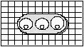
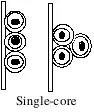
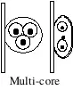
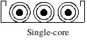
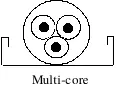
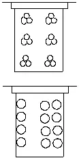
2.7.4.3 Methods of installation of cables and conductors in common use are specified in Table 8.2.10.
Table 8.2.10
Methods of Installation of Cables and Conductors in Common Use
|
Type |
Description |
Example | |
|
A |
Cables enclosed in conduit | ||
|
B |
Cables enclosed in trunking |

|

|
|
C |
Cables enclosed in underground conduit, ducts, and cable ducting. |

|

|
|
D |
Two or more single-core cables contained in separate bores of a multi-core conduit and intended to be solidly embedded in concrete or plaster or generally incorporated in the building structure. |
| |
|
E |
Sheathed cables clipped direct to a nonmetallic surface. |
|
|
|
F |
Sheathed cables on a cable tray. |
|
|
|
G |
Sheathed cables embedded direct in plaster. |

|

|
|
(Continued to next page) | |||
Table 8.2.10 (Contd.)
Methods of Installation of Cables and Conductors in Common Use
|
H |
Sheathed cables suspended from or incorporating a catenary wire. |

| |
|
J |
Sheathed cables in free air. |
| |
|
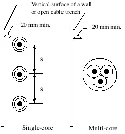
For cables in which the conductor cross-sectional area does not exceed 185 mm2, S is equal to twice the overall diameter of the cable. For cables in which the conductor cross-sectional area exceeds 185 m2, S is about 90 mm. For two cables in horizontal formation on brackets fixed to a wall, S may have any lesser value. | |||
|
K |
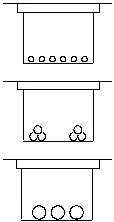
Single and multi-core cables in enclosed trench 450 mm wide by 600 mm deep (minimum dimensions) including 100 mm cover. |
Two single-core cables with surfaces separated by a distance equal to one diameter; three single-core cables in trefoil and touching throughout. Multi-core cables or groups of single-core cables separated by a minimum distance of 50 mm. |
|
(Continued to next page)
Table 8.2.10 (Contd.)
Methods of Installation of Cables and Conductors in Common Use
|
L |
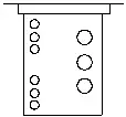
Single and multi-core cables in enclosed trench 450 mm wide by 600 mm deep (minimum dimensions) including 100 mm cover. |
Single-core cables arranged in flat groups of two or three on the vertical trench wall with surfaces separated by a distance equal to one diameter with a minimum separation of 50 mm between groups. Multi-core cables installed singly separated by a minimum* distance of 75 mm. All cables spaced at least 25 mm from the trench wall. |
|
|
M |
Single and multi-core cables in enclosed trench 600 mm wide by 760 mm deep (minimum dimensions) including 100 mm cover. |
Single-core cables arranged in groups of two or three in flat formation with the surfaces separated by a distance equal to one diameter or in trefoil formation with cables touching. Groups separated by a minimum* distance of 50 mm either horizontally or vertically. Multi-core cables installed singly separated by a minimum* distance of 75 mm either horizontally or vertically. All cables spaced at least 25 mm from the trench wall. |
|
|
* Larger spacing to be used where practicable. | |||
2.7.4.4 Ducts cast-in-situ in concrete, by means of a suitable former laid before the concrete is poured, into which cables are to be drawn (whether or not the former are retained in position after the concrete has set) shall be so formed that the radial thickness of concrete surrounding the cross-section of the completed duct is not less than 15 mm at any point.
2.7.5 Main Switch and Switchboards
2.7.5.1 All main switches shall be either of metal clad enclosed pattern or of any insulated enclosed pattern and the switches shall be fixed at close proximity to the point of entry of supply.
2.7.5.2 There shall be circuit breakers or miniature circuit breakers or load break switch fuses on each live conductor of the supply mains at the point of entry. The wiring throughout the installation shall be such that there is no break in the neutral wire in the form of a switch or fuse unit or otherwise.
2.7.5.3 Location
a) The location of the main board shall be such that it is easily accessible for firemen and other personnel to quickly disconnect the supply in case of emergencies.
b) Main switchboards shall be installed in boxes or cupboards so as to safeguard against operation by unauthorized personnel.
c) Open type switchboards shall be placed only in dry locations and in ventilated rooms and they shall not be placed in the vicinity of storage batteries or exposed to chemical fumes.
d) In damp situation or where inflammable or explosive dust, vapour or gas is likely to be present, the switchboard shall be totally enclosed or made flame proof as may be necessitated by the particular circumstances.
e) Switchboards shall not be erected above gas stoves or sinks, or within 2.5 m of any washing unit in the washing rooms or laundries.
f) In case of switchboards being unavoidable in places likely to be exposed to weather, to drip, or in abnormally moist atmosphere, the outer casing shall be weather proof and shall be provided with glands or bushings or adapted to receive screwed conduit.
g) Adequate illumination shall be provided for all working spaces about the switchboards, when installed indoors.
2.7.5.4 Metal clad switchgear shall be mounted on hinged type metal boards or fixed type metal boards.
a) Hinged type metal boards shall consist of a box made of sheet metal not less than 2 mm thick and shall be provided with a hinged cover to enable the board to swing open for examination of the wiring at the back. The joints shall be welded. The board shall be securely fixed to the wall by means of rag bolt plugs, or wooden plugs and shall be provided with locking arrangement and an earthing stud. All wires passing through the metal board shall be protected by a rubber or wooden bush at the entry hole. The earth stud should be commensurate with the size of the earth lead(s).
b) Fixed type metal boards shall consist of an angle or channel steel frame fixed on the wall at the top, if necessary.
c) There shall be a distance of one metre clear in front of the switchboards.
2.7.5.5 Wooden Boards : For small installations connected to a single-phase 240 volts supply, wooden boards may be used as main boards or sub-boards. These shall be of seasoned teak or other approved quality timber with all joints dovetailed.
2.7.5.6 Location of Distribution Boards : The distribution fuse boards shall be located as near as possible to the centre of the load they are intended to control.
a) They shall be fixed on suitable stanchion or wall and shall be accessible for replacement of fuses, and shall not be more than 2 m from floor level.
b) They shall be either metal clad type, or all insulated type. But if exposed to weather or damp situations, they shall be of the weather proof type and if installed where exposed to explosive dust, vapour or gas, they shall be of flame proof type. In corrosive atmospheres, they shall be treated with anticorrosive preservative or covered with suitable plastic compounds.
c) Where two or more distribution fuse boards feeding low voltage circuits are fed from a supply of medium voltage, these distribution boards shall be :
- fixed not less than 2 m apart, or
- arranged so that it is not possible to open two at a time, namely, they are interlocked, and the metal case is marked "Danger 415 Volts" and identified with proper phase marking and danger marks, or
- installed in rooms or enclosures accessible to authorized persons only.
d) All distribution boards shall be marked "Lighting" or "Power", as the case may be, and also be marked with the voltage and number of phases of the supply. Each shall be provided with a circuit list giving diagram of each circuit which it controls and the current rating for the circuit and size of fuse element.
2.7.6 Protection of Circuits
2.7.6.1 Appropriate protection shall be provided at switchboards and distribution boards for all circuits and sub-circuits against short circuit and overcurrent and the protective apparatus shall be capable of interrupting any short circuit current that may occur, without danger. The ratings and settings of fuses and the protective devices shall be coordinated so as to afford selectivity in operation.
2.7.6.2 Where circuit breakers are used for protection of main circuit and the sub-circuits derived therefrom, discrimination in operation shall be achieved by adjusting the protective devices of the sub-main circuit breakers to operate at lower current settings and shorter time-lag than the main circuit breaker.
2.7.6.3 A fuse carrier shall not be fitted with a fuse element larger than that for which the carrier is designed.
2.7.6.4 The current rating of fuses shall not exceed the current rating of the smallest cable in the circuit protected by the fuse.
2.8 EARTHING
2.8.1 General
The object of an earthing system is to provide a system of conductors, as nearly as possible at a uniform and zero, or earth, potential. The purpose of this is to ensure that, in general, all parts of equipment and installation other than live parts shall be at earth potential, thus ensuring that persons coming in contact with these parts shall also be at earth potential at all times.
2.8.2 Circuit and System Earthing
2.8.2.1 The purpose of circuit and system earthing is to limit excessive voltage from line surges, from cross-overs with higher voltage lines, or from lightning, and to keep non current carrying enclosures and equipment at zero potential with respect to earth. Earthing the system helps facilitate the opening of overcurrent protection devices in case of earth faults.
Earthing associated with current carrying conductors is normally essential for the security of the system and is generally known as system earthing, while earthing of non-current carrying metal work and conductor is essential for the safety of human life, animals, and property and it is generally known as equipment earthing.
2.8.2.2 The earthing arrangements shall be such that :
- the value of resistance from the consumer's main earthing terminal to the earthed point of the supply, or to earth, is in accordance with the protective and functional requirements of the installation, and expected to be continuously effective,
- earth fault currents and earth leakage currents likely to occur are carried without danger, particularly from the point of view of thermal, thermomechanical and electromechanical stresses.
2.8.2.3 Precautions shall be taken against the risk of damage to other metallic parts through electrolysis.
2.8.2.4 Where a number of installations have separate earthing arrangements, protective conductors running between any two of the separate installations shall either be capable of carrying the maximum fault current likely to flow through them, or be earthed within one installation only and insulated from the earthing arrangements of any other installation. In the latter circumstances, if the protective conductor forms part of a cable, the protective conductor shall be earthed only in the installation containing the associated protective device.
2.8.3 Methods of Earthing
2.8.3.1 The usual method of earthing is to join the exposed metal work to earth via an earth continuity conductor connected to an electrode buried in the ground. In conjunction with a fuse, or other similar device, this then forms a protective system. Thus, if a live conductor accidentally comes into contact with an exposed metal, the fuse or protective device operates. As long as the overall resistance of the protective system is low, a large fault current flows which blows the fuse. This cuts off the supply and isolates the faulty circuit, preventing risk of shock, fire, or damage to equipment/installation.
2.8.3.2 The three main elements required for an earthing system are earth conductors, earthing lead and earth electrodes. The method of connecting earth wires, earthing lead and earth electrodes is as important as the selection of the main elements because poor connection will render the earthing system ineffective.
2.8.3.3 Earth Conductors : This is the part of the earthing system which joins or bonds together all the metal parts of an installation.
a) In all cases the grounding conductor shall be made of copper or galvanized steel or other metals or combination of metals which will not corrode excessively and, if practical, shall be without joints or splice. If joints are unavoidable, they shall be made and maintained so as not to materially increase the resistance of the earthing conductor and shall have appropriate mechanical and corrosion resistant characteristics. Where the earth conductor is to be buried underground in corrosive soil, use of insulated cable as earth conductor is to be preferred.
b) Aluminium or copper clad aluminium conductors shall not be used for final connections to earth electrodes.
c) The earth conductor shall have a short time capacity adequate for the fault current which can flow in the grounding conductor or conductors for the operating time of the system protective device. In case of copper wire being used as earth conductors, the size of the wire shall not be less than half the area of the largest current carrying conductor supplying the circuit.
d) Table 8.2.11 gives the minimum sizes of copper earth conductors corresponding to the sizes of associated copper circuit conductors. No size smaller than 14 SWG (3.243 mm2) shall be used anywhere as earth conductor.
2.8.3.4 Earth Lead
a) Earth lead is the link which provides connection between the earth conductor(s) and the earth electrode(s). The earth conductors shall be brought to one or more connecting points, according to size of installation; the copper wire earthing leads shall run from there to the electrodes.
b) Earthing lead can either be of copper wire or of copper strip. Other metals can also be used as in case of earth conductors.
c) Earthing leads shall be run in duplicate down to the earth electrode so as to increase the safety factor of the installation. Copper wire used as earthing lead must not be smaller than 8 SWG (12 mm2) .
Table 8.2.11
Minimum Cross-sectional Area of Copper Earth Conductors in Relation to
the Area of Associated Phase Conductors
|
Cross-sectional Area of Phase Conductor(s) (mm2) |
Minimum Cross-sectional Area of the Corresponding Earth Conductor (mm2) |
|
Less than 16 16 or greater but less than 35 35 or greater |
Same as cross-sectional area of phase conductor but not less than 14 SWG 16 Half the cross-sectional area of phase conductor |
2.8.3.5 Earth Electrodes
a) The earth electrode shall, as far as practicable, penetrate into permanently moist soil preferably below ground water table. The resistance of earth electrodes shall not be more than one ohm.
b) The following types of earth electrodes are recognized for the purpose of this Code :
- Copper rods,
- Copper plates,
- Galvanized iron pipes.
c) Details of typical pipe and plate earth electrodes are given in Fig 8.2.1 and 8.2.2. The following is a guideline for electrode size :
- Copper rods shall have a minimum diameter of 12.7 mm,
- GI pipes shall have a minimum diameter of 50 mm,
- Copper plates shall not be less than 600 mm x 600 mm in size, with 6 mm thickness.
2.9 LIGHTNING PROTECTION OF BUILDINGS
2.9.1 General
Whether a building needs protection against lightning is a matter of judgement on the part of the designer; obviously it depends on the probability of a stroke and acceptable risk levels. For example, a higher risk is presumably acceptable for an isolated small bungalow than, say, for a children's hospital. Whilst no exact rules can be laid down which would eliminate the designer's judgement entirely, certain steps can be taken for an objective assessment of the risk and of the magnitude of the consequences. As an aid to making a judgement, a set of indices is given in Table 8.2.12 and elaborated in Sec 2.9.1.1 to 2.9.1.7 below for the various factors involved.
2.9.1.1 Usage of Structure : The lightning hazard to human beings within a structure or a building is a very important factor in deciding how far to go in providing lightning protection. Schools, hospitals, auditoriums, railway stations, etc., are places where a large number of people congregate and, therefore, would in general be structures of greater importance than small buildings and houses.
2.9.1.2 Type of Construction : The type of construction of the structure has a large influence upon the extent of protection to be provided. A steel framed building to some extent is self-protecting and may not generally require additional protection, while brick buildings or buildings with thatched roof require greater degree of protection.
2.9.1.3 Contents or Consequential Effects : In addition to direct loss due to destruction of buildings by lightning, fire resulting from lightning , killing of livestock, etc. there may be indirect losses which sometimes accompany the destruction of buildings and their contents. An interruption to business or to farming operations, specially at certain times of the year, may involve losses quite distinct from, and in addition to, the losses arising from the direct destruction of property. There are also cases where whole community depends for safety and comfort in some respect on the integrity of a single structure, as for instance on the brick chimney of a water pumping plant. A lightning strike to it may have a serious consequence due to disruption of sanitary facilities, drinking water, water for irrigation, fire protection, etc. The contents of buildings should also be considered as to whether they are replaceable, explosive, combustible, flammable vapour or explosive dust. These may present a hazard in a building that is otherwise immune to lightning. Contents like hay or cotton may make protection measures specially desirable.
2.9.1.4 Degree of Isolation : The relative exposure of a particular building will be an element in determining whether the expense of lightning protection is warranted. In closely built-up towns and cities, the hazard is not as great as in the open country.
Fig 8.2.1
Fig 8.2.2
Table 8.2.12
Index Figures Associated with Lightning Protection Design
Index A: Use of Structure Index
Houses and similar buildings 2
Houses and similar buildings with outside aerial 4
Small and medium size factories, workshops and laboratories 6
Big industrial plants, telephone exchanges, office blocks, 7
hotels, blocks of flats
Places of assembly, for example, places of workshop, halls, 8
theatres, museums, exhibitions, department stores,
post offices, stations, airports, stadiums
Schools, hospitals, children's homes and other such structures 10
Index B: Type of Construction
Steel framed encased with nonmetal roofa 1
Reinforced concrete with nonmetal roof 2
Brick, plain concrete, or masonry with nonmetal roof 4
Steel framed encased or reinforced concrete with metal roof 5
Timber formed or clad with any roof other than metal or thatch 7
Any building with a thatched roof 10
aA structure of exposed metal which is continuous down to ground
level is excluded from the table as it requires no lightning protection
beyond adequate earthing arrangements.
Index C: Contents or Consequential Effects
Ordinary domestic or office building, factories and 2
workshops not containing valuable materials
Industrial and agricultural buildings with specially susceptibleb 5
contents
Power stations, gas works, telephone exchanges, radio stations 6
Industrial key plants, ancient monuments, historic 8
buildings, museums, art galleries
Schools, hospitals, children's and other homes, places of assembly 10
b This means specially valuable plant or materials vulnerable to fire
or the results of fire.
Index D: Degree of Isolation
Structure located in a large area having structures or trees of similar
or greater height, e.g. a large town or forest 2
Structure located in an area with a few other structures or trees of 5
similar height
Structure completely isolated or exceeding at least twice 10
the height of surrounding structures or trees
(Continued to next page)
Table 8.2.12 (Contd.)
Index Figures Associated with Lightning Protection Design
Index E: Type of Terrain
Flat terrain at any level 2
Hilly terrain 6
Mountainous terrain 300 m and above 8
Index F: Height of Structure
Up to 9 m 2
9-15 m 4
15-18 m 5
18-24 m 8
24-30 m 11
30-38 m 16
38-46 m 22
46-53 mc 30
c Structures higher than 53 m require protection in all cases.
Index G: Lightning Prevalence
Number of thunderstorm days per year :
Up to 3 2
4-6 5
7-9 8
10-12 11
13-15 14
16-18 17
19-21 20
Over 21 21
2.9.1.5 Type of Terrain : In hilly or mountainous areas, buildings are more susceptible to damage due to lightning than buildings in the plains or flat terrain. In hilly areas, a building upon high ground is usually subject to greater hazard than one in a valley or otherwise sheltered area.
2.9.1.6 Height of Structure : Height of the structure is an important factor for the purpose of lightning protection. Taller structures are subject to greater hazards than smaller structures and, therefore, lightning protection is more desirable for tall structures.
2.9.1.7 Lightning Prevalence : The number of thunderstorm days in a year varies in different parts of a country. However, the severity of lightning storms, as distinguished from their frequency of occurrence, is usually much greater in some locations than others. Hence, the need for protection varies from place to place, although not necessarily in direct proportion to the thunderstorm frequency.
2.9.2 Risk Assessment
"Risk Index" is the sum of the indices for all the factors, as given in Table 8.2.12. A few examples of calculation of Risk Index are given in Table 8.2.13, based on a marginal Risk Index of 40.
2.9.3 Number of Arresters Required and their Installation
2.9.3.1 A complete lightning protection system consists of an air termination network, a down conductor and an earth termination. The air termination network is that part which is intended to intercept lightning discharges. It consists of vertical and horizontal conductors arranged to protect the required area.
2.9.3.2 The zone of protection is the space within which a lightning conductor provides protection by attracting the stroke to itself. It has been found that a single vertical conductor attracts to itself strokes of average or above average intensity which in the absence of the conductor would have struck the ground within a circle having its centre at the conductor and a radius equal to twice the height of the conductor. For weaker than average discharges the protected area becomes smaller. For practical design it is therefore assumed that statistically satisfactory protection can be given to a zone consisting of a cone with its apex at the top of the vertical conductor and a base radius equal to the height of the conductor. This is illustrated in Fig 8.2.3.
2.9.3.3 A horizontal conductor can be regarded as a series of apexes coalesced into a line, and the zone of protection thus becomes a tentlike space (Fig 8.2.4).
Table 8.2.13
Example of Calculation of Risk Index
|
Example |
A |
B |
C |
D |
E |
F |
G |
Total Index Figure |
Recommen- dations |
|
Small residential building in a thickly populated locality (height less than 10 m) |
2 |
4 |
2 |
2 |
2 |
2 |
21 |
35 |
No protection needed, in general |
|
Office building in a locality (height 20 m) |
7 |
2 |
2 |
2 |
2 |
5 |
21 |
41 |
As the figure is around 40, need of protection will depend upon the importance of the building |
|
Hotel building (height 31m) exceeding twice the height of surrounding structures |
7 |
2 |
2 |
10 |
2 |
16 |
21 |
60 |
Protection essential |
|
Building of historical importance completely isolated (height exceeding 55 m) |
8 |
4 |
8 |
10 |
2 |
30 |
21 |
83 |
Protection essential |
|
Structure of high historical importance (height exceeding 55 m) |
- |
- |
- |
- |
- |
- |
- |
- |
Protection essential as the height exceeds 53 m |
|
Structure, such as hydro-electric power stations, sufficiently protected by means of surrounding structures, for example, high vertical cliffs, high metallic structures or earth wire of transmission system (height 15 m) |
7 |
2 |
6 |
2 |
6 |
4 |
21 |
48 |
Protected by surroundings |
2.9.3.4 When there are several parallel horizontal conductors the area between them has been found by experience to be better protected than one would expect from the above considerations only. The recommended design criterion is that no part of the roof should be more than 9 m from the nearest horizontal conductor except that an additional 0.3 m may be added for each 0.3 m or part thereof by which the part to be protected is below the nearest conductor.
2.9.3.5 The earth termination is that part which discharges the current into the general mass of the earth. In other words, it is one or more earth electrodes. Earth electrodes for lightning protection are no different from earth electrodes for short circuit protection systems. The total resistance of an electrode for a lightning protection system must not exceed 10 ohms.
2.9.3.6 The down conductor is the conductor which runs from the air termination to the earth termination. A building with a base area not exceeding 100 m2 shall be provided with one down conductor. For a larger building, there shall be one down conductor for the first 100 m2 plus a further one for every 300 m2 or par thereof in excess of the first 100 m2. Alternatively, for a larger building one down conductor may be provided for every 30 m of perimeter. The number chosen can be the smaller of the numbers given by these alternative methods of calculation.
2.9.3.7 The material used for lightning conductors must be aluminium or copper. The criterion for design is to keep the resistance from air termination to earth to a minimum.
2.9.3.8 Recommended dimensions for various components of lightning arrester are given in Table 8.2.14. Larger conductors should however be used if the system is unlikely to receive regular inspection and maintenance.
Fig 8.2.3 & 8.2.4
Table 8.2.14
Sizes of the Components of Lightning Protection Systems
|
Components |
Minimum Dimensions |
|
Air Terminations Aluminium and copper strip Aluminium, aluminium alloy, copper and phosphor bronze rods Stranded aluminium conductors Standard copper conductors |
20 mm x 3 mm 10 mm dia 19 strands of 2.5 mm 19 strands of 1.8 mm |
|
Down Conductors Aluminium and copper strip Aluminium, aluminium alloy and copper rods |
20 mm x 3 mm 10 mm dia |
|
Earth Terminations Hard drawn copper rods for driving into soft ground Hard drawn or annealed copper rods for indirect driving or laying in ground Phosphor bronze for hard ground Copper clad steel for hard ground |
12 mm dia 10 mm dia 12 mm dia 10 mm dia |
2.9.3.9 External metal on a building should be bonded to the lightning conductor with bonds at least as large as the conductor.
2.9.3.10 When a lightning conductor carries a stroke to earth, it is temporarily raised to a potential considerably above that of earth. There is, therefore, a risk that the discharge will flash over to nearby metal and cause damage to the intervening structure. This can be prevented by either providing sufficient clearance between conductor and other metal or by bonding these together to ensure that there can be no potential difference between them. The necessary clearance is obtained from:
Next 'div' was a 'text:p'. Next 'span' is a draw:frame. (2.9.1)where
D = clearance in metres
R = resistance to earth in ohms
H = height of building in metres
n = number of down electrodes
Since it is often impracticable to provide the necessary clearance, the alternative technique of bonding is preferred.
2.9.4 Surge Arrester Selection
2.9.4.1 A surge arrester is a protective device for limiting surge voltages by discharging, or bypassing, surge current through it; it also prevents continued flow of follow-through current while remaining capable of repeating these functions. It is used to protect overhead lines and other electrical apparatus, viz. transforming from overhead voltages and lightning.
2.9.4.2 Horn-gap lightning arresters are commonly used for low and medium voltage overhead lines. The rating of the surge arrester shall be equal to or greater than the maximum continuous phase to ground power frequency voltage available at the point of application.
2.10 TELECOMMUNICATION AND MISCELLANEOUS SERVICES
2.10.1 General
Internal wiring of telephone lines in small buildings is normally undertaken during installation of individual sets. But in large multi-storeyed buildings intended for commercial, business and office use as well as for residential purposes, wiring for telephone connections is generally done beforehand through concealed conduits during construction of the building itself.
In multi-storeyed apartments, houses and hotels where many TV receivers are located, a common master antenna system is often used to avoid mushrooming of individual antennas. Master antenna is generally provided at the topmost convenient point in any building and a suitable room on the topmost floor or terrace for housing the amplifier unit etc., may also be provided in consultation with the architect/engineer.
2.10.2 Telecommunication Circuits
The design of telephone systems is beyond the scope of this Code, but the provision that has to be made for them within a building must be considered. In many cases all that is needed is a route by which the telephone service can bring in a telephone cable to an instrument. Telephone cables are quite small and if the position of the outlet for the telephone receiver is known it is sufficient to install a 20 mm conduit from outside the building to the outlet, with the same number and spacing of draw-in points as are used for any other conduit system. Some buildings may have an internal telephone system which may consist of extensions to the public telephones or may be an entirely separate installation. Here again the essential matter for the electrical services designer is to agree on the outlet positions with his customer and to arrange for them to be linked to each other by conduit or trunking. Trunking can be a useful alternative to conduit when the system is a complex one needing many cables with a large number of junctions. Telephone cables do not have a protective sheathing and therefore need the mechanical protection of conduit or trunking. Where practicable, a separation of at least 1.8 m shall be maintained between open conductors of communication systems on buildings and the lightning conductors.
2.10.3 Television Antennas
If every tenant in a block of flats had his own TV antenna on the roof of the building, the result would be very unsightly. It is an advantage to receive television or radio signals at one suitably sited antenna array and relay them to individual dwellings by cables or transmission lines.
Lead-in cable must be installed with care to prevent damage to the cable. The various connections and splices must be made carefully. Where practicable, a separation of at least 92 m is to be maintained so as not to change the spacing of the conductors within the cable. Such changes result in a distorted television signal. Shielded lead in cables may be run in or near metal objects without affecting television reception. Unshielded lead-in wires installed close to these items may affect reception.
2.11 INSPECTION AND TESTING
2.11.1 General
2.11.1.1 Every installation shall, on completion and before being energized, be inspected and tested. The methods of test shall be such that no danger to persons or property or damage to equipment occurs even if the circuit tested is defective.
2.11.1.2 Periodic inspection and testing shall be carried out in order to maintain the installation in a sound condition after putting it into service. Where an addition is to be made to the fixed wiring of an existing installation, the latter shall be examined for compliance with the recommendations of the Code.
2.11.1.3 The individual equipment and materials which form part of the installation shall generally conform to the relevant Bangladesh Standard (BDS) wherever applicable. If there is no relevant Bangladesh standard specification for any item, these shall be approved by the appropriate authority.
2.11.2 Insulation Tests
2.11.2.1 Insulation resistance test shall be made on all electrical equipment, using a self-contained instrument such as the direct indicating ohm-meter of the generator type. d.c. potential shall be used in these tests and shall be as follows:
Circuits under 230 volts 500 volts
Circuits between 230 volts to 400 volts 1000 volts
2.11.2.2 The minimum acceptable insulation resistance value is 5 mega ohms. Before making connections at the ends of each cable run, the insulation resistance measurement test of each cable shall be made. Each conductor of a multi-core cable shall be tested individually to all other conductors of the group and also to earth. If insulation resistance test readings are found to be less than the specified minimum in any conductor, the entire cable shall be replaced.
2.11.2.3 All transformers, switchgears etc. shall be subject to an insulation resistance measurement test to ground after installation but before any wiring is connected. Insulation tests shall be made between open contacts of circuit breakers, switches etc. and between each phase and earth.
2.11.3 Earth Resistance Test
2.11.3.1 Earth resistance tests shall be made on the system, separating and reconnecting each earth connection.
2.11.3.2 The electrical resistance of the earth continuity conductor together with the resistance of the earthing lead measured from the connection with the earth electrode to any other position in the completed installation shall not exceed 1 ohm.
2.11.3.3 Where more than one earthing sets are installed, the earth resistance between two sets shall be measured by means of resistance bridge instrument. The earth resistance between two sets shall not exceed 1 ohm.
2.11.4 Operating Tests
Current load measurement shall be made on equipment and on all power and lighting feeders. The current reading shall be taken in each phase wire and in each neutral wire while the circuit or equipment is operating under actual load conditions. Clip-on ammeters may be used to take current readings. All light fittings shall be tested electrically and mechanically to check whether they comply with the standard specifications. Fluorescent light fittings shall be tested so that when functioning no flickering or choke singing is felt.
2.11.5 Inspection of the Installation
On completion of wiring a general inspection shall be carried out by competent personnel in order to verify that the provisions of this Code and that of the Electricity Act of Bangladesh have been complied with. A certificate may be issued on satisfactory completion of the work in a format as shown in Appendix C. Items to be inspected are detailed in the following sections.
2.11.5.1 Substation Installations : In substation installations, it shall be checked whether:
- The installation has been carried out in accordance with the approved drawings;
- Phase to phase and phase to earth clearances are provided as required;
- All equipment are efficiently earthed and properly connected to the required number of earth electrodes;
- The required ground clearance to live terminals is provided;
- Suitable fencing is provided with gate with lockable arrangements;
- The required number of caution boards, fire fighting equipment, operating rods, rubber mats, etc., are kept in the substation;
- In case of indoor substation sufficient ventilation and draining arrangements are made;
- All cable trenches are provided with noninflammable covers;
- Free accessibility is provided for all equipment for normal operation;
- All name plates are fixed and the equipment are fully painted;
- All construction materials and temporary connections are removed;
- Oil level , bus bar tightness, transformer tap position, etc. are in order;
- Earth pipe troughs and cover slabs are provided for earth electrodes/earth pits and the neutral and LA earth pits are marked for easy identification;
- Earth electrodes are of GI pipes or CI pipes or copper plates. For earth connections, brass bolts and nuts with lead washers are provided in the pipes/plates;
- Earth pipe troughs and oil sumps/pits are free from rubbish, dirt and stone jelly and the earth connections are visible and easily accessible;
- HT and LT panels and switchgears are all vermin and damp-proof and all unused openings or holes are blocked properly;
- The earth bus bars have tight connections and corrosion free joint surfaces;
- Control switch fuses are provided at an accessible height from ground;
- Adequate headroom is available in the transformer room for easy topping-up of oil, maintenance, etc.;
- Safety devices, horizontal and vertical barriers, bus bar covers/shrouds, automatic safety shutters/door interlock, handle interlock etc. are safe and in reliable operation in all panels and cubicles;
- Clearances in the front, rear and sides of the main HT and LT and subswitch boards are adequate;
- The switches operate freely; the 3 blades make contact at the same time, the arcing horns contact in advance; and the handles are provided with locking arrangements,
- Insulators are free from cracks, and are clean;
- In transformers, there is no oil leak;
- Connections to bushing in transformers are light and maintain good contact;
- Bushings are free from cracks and are clean;
- Accessories of transformers like breathers, vent pipe, buchholz relay, etc. are in order;
- Connections to gas relay in transformers are in order;
- In transformers, oil and winding temperature are set for specific requirements to pump out;
- In case of cable cellars, adequate arrangements exist to pump off water that has entered due to seepage or other reasons; and
- All incoming and outgoing circuits of HT and LT panels are clearly and indelibly labeled for identifications.
2.11.5.2 Medium Voltage Installation : In medium voltage installations, it shall be checked whether:
- All blocking materials that are used for safe transportation in switchgears, contactors, relays, etc. are removed;
- All connections to the earthing system are feasible for periodical inspection;
- Sharp cable bends are avoided and cables are taken in a smooth manner in the trenches or alongside the walls and ceilings using suitable support clamps at regular intervals;
- Suitable linked switch or circuit breaker or lockable push button is provided near the motors/apparatus for controlling supply to the motor/apparatus in an easily accessible location;
- Two separate and distinct earth connections are provided for the motor apparatus;
- Control switch fuse is provided at an accessible height from ground for controlling supply to overhead travelling crane, hoists, overhead bus bar trunking;
- The metal rails on which the crane travels are electrically continuous and earthed and bonding of rails and earthing at both ends are done;
- Four-core cables are used for overhead travelling crane and portable equipment, the fourth core being used for earthing, and separate supply for lighting circuit is taken;
- If flexible metallic hose is used for wiring to motors and other equipment, the wiring is enclosed to the full lengths, and the hose secured properly by approved means;
- The cables are not taken through areas where they are likely to be damaged or chemically affected;
- The screens and armours of the cables are earthed properly;
- The belts of belt driven equipment are properly guarded;
- Adequate precautions are taken to ensure that no live parts are so exposed as to cause danger;
- Ammeters and voltmeters are tested; and
- The relays are inspected visually by moving covers for deposits of dusts or other foreign matter.
2.11.5.3 Overhead Lines : For overhead lines, it shall be checked whether:
- All conductors and apparatus including live parts thereof are inaccessible;
- The types and size of supports are suitable for the overhead lines/conductors used and are in accordance with approved drawing and standards;
- Clearances from ground level to the lowest conductor of overhead lines, sag conditions, etc. are in accordance with the relevant standard;
- Where overhead lines cross the roads or cross each other or are in proximity with one another, suitable guarding is provided at road crossings and also to protect against possibility of the lines coming in contact with one another;
- Every guard wire is properly earthed;
- The type, size and suitability of the guarding arrangement provided is adequate;
- Stays are provided suitably on the overhead lines as required and are efficiently earthed or provided with suitable stay insulators of suitable voltages;
- Anticlimbing devices and Danger Board/Caution Board Notices are provided on all HT supports;
- Clearances along the route are checked and all obstructions such as trees/branches and shrubs are cleared on the route to the required distance on either side;
- Clearance between the live conductor and the earthed metal parts are adequate; and
- For the service connections tapped off from the overhead lines, cutouts of adequate capacity are provided.
2.11.5.4 Lighting Circuits : The lighting circuits shall be checked to see whether:
- Wooden boxes and panels are avoided in factories for mounting the lighting boards, switch controls, etc.;
- Neutral links are provided in double pole switch fuses which are used for lighting control, and no fuse is provided in the neutral;
- The plug points in the lighting circuit are all 3-pin type, the third pin being suitably earthed;
- Tamper proof interlocked switch socket and plug are used for locations easily accessible;
- Lighting wiring in factory area is enclosed in conduit and the conduit is properly earthed, or alternatively, armoured cable wiring is used;
- A separate earth wire is run in the lighting installation to provide earthing for plug points, fixtures and equipment;
- Proper connectors and junction boxes are used wherever joints are in conductors or cross over of conductors takes place;
- Cartridge fuse units are fitted with cartridge fuses only;
- Clear and permanent identification marks are painted in all distribution boards, switchboards, sub-main boards and switches as necessary;
- The polarity has been checked and all fuses and single pole switches are connected on the phase conductor only and wiring is correctly connected to socket outlets;
- Spare knockouts provided in distribution boards and switch fuses are blocked;
- The ends of conduits enclosing the wiring leads are provided with ebonite or other suitable bushes;
- The fittings and fixtures used for outdoor use are all of weatherproof construction, and similarly, fixtures, fittings and switchgears used in the hazardous area are of flameproof application;
- Proper terminal connectors are used for termination of wires (conductors and earth leads) and all strands are inserted in the terminals;
- Flat ended screws are used for fixing conductor to the accessories;
- Flat washers backed up by spring washers are used for making end connections.
Related Appendices
Appendix A Maximum Demand and Diversity
Appendix B Useful Tables Relating to Conductor Sizes
Appendix C Completion Certificate Form
This page is intentionally left blank.
Source: Bangladesh National Building Code 2006 (Housing and Building Research Institute). Superseded by BNBC 2020 — provided for reference. For design or official work, refer to the printed code.